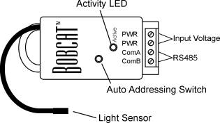
Light Sensor Bobcat™
Introduction
The
Light Sensor Bobcat™ is a single point module providing light level readings.
Specifications
Power: Input Voltage 9 - 12V DC or AC
Input Current Max 30mA
Dimensions: 1.3”W x 2.5”L x 0.6”D
Probe Cable 18”
Operating
Temperature: Bobcat™ 32ºF to 158ºF
Sensor -40ºF to 167ºC
Setup
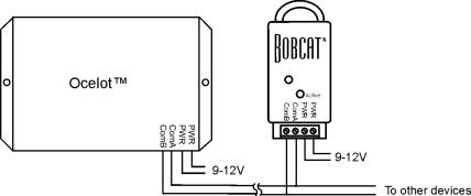
Figure 1. Typical Wiring Diagram
Note: The Bobcat™ may be used outdoors but must be installed in an area so that it will not get wet!
Operation
LED Codes
ON solid – Bobcat™ has not been addressed
Slow Blink – Bobcat™ has a valid address
Fast Blink – Auto address mode active
On solid, then Rapid blink - ADICON™ communications active
|
Parameter |
Function |
|
1 |
Module Address |
|
2 |
Bright Threshold |
|
3 |
Dark Threshold |
|
5 |
Returned Data Mode 1 = Light Level, 0 = Light/Dark Mode (default) |
Table 1. Light Sensor Bobcat™ Parameters
Light Sensor Bobcat™ Data Modes
Analog Mode
When parameter 5 is set to a 1, the Light Sensor Bobcat™ will return a value (0 – 255) based on the amount of light falling on the sensor. A return value of 255 is maximum brightness.
Digital Mode
When parameter 5 is set to 0 (factory default) the Light Sensor Bobcat™ will return a 1 or 0 based on comparing the light level to the threshold values. When the light level is greater than the Bright Threshold the Bobcat™ will return a 1. When the light level is less than the Dark Threshold the Bobcat™ will return a 0. The return value will not change until the light level has crossed a threshold and remained there for 10 seconds.
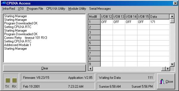
Viewing Bobcat™ Data
The CPUXA access screen of C-Max™ now has a data field to show the decimal value of data returned by a module. To view the data field, move the horizontal scroll bar all the way to the right. See the sample screen below. Data shown for a Bobcat™ module will be offset by 100, that is, the value shown is 100 greater than the actual data.
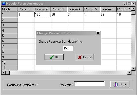
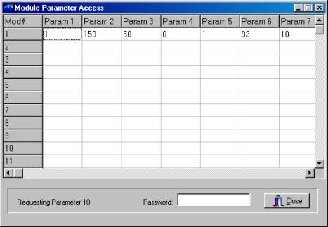
Setting Threshold Values
The threshold values are stored in parameters 2 and 3 (see Table 2). C-Max™ is used to change a parameter value. Below is a sample screen of the Module parameter utility. For more information
about changing module parameters see the application note Changing Module Parameters.
Accessing the Bobcat™ data
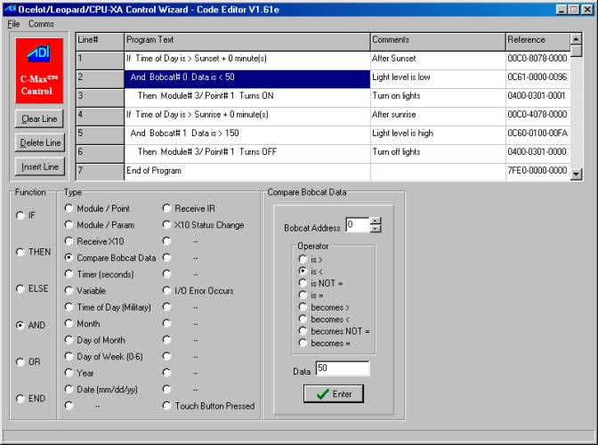
Analog Input Example: Using a light sensor to turn outside lights on and off
Parameter 5 of the Light Sensor Bobcat™ must be set to 1 to use analog mode. Now determine the threshold voltages of when you want the lights to turn on and off. For our example we will use 50 to turn the lights on and 150 to turn the lights off. The code example below shows how to turn the lights off after sunrise only if there is enough light and turn the lights off after dusk when dark enough. In this example, the more light on the sensor the smaller the analog reading.
Example of Digital Input
Using the threshold calculated in the above example lets now use the Light Sensor Bobcat™ in digital mode by setting parameter 5 to 0. Use C-Max™ to program parameters 2 and 3 to the thresholds calculated in previous example.
Now we write a program to turn the
light off when the Bobcat™ returns a 1 and turn them on when the Bobcat™
returns a 0.
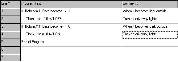
In this example the returned value will not change until the light level has crossed a threshold and remained there for 10 seconds.