RLY8-XA™
Introduction
The RLY8-XA™ module provides
8 high current relay outputs. The
RLY8-XA™ can be controlled by either the ADICON™ 2500 or X10 communication
protocols. To use the X10 protocol a
TW523 module must be connected to the RLY8-XA™.
Specifications
Power: Input Voltage 9 - 16V DC or AC
Input Current Max 800mA
I/O: Relay Output: Form C, 120V 10A, 220V 5A
X10 Input: RJ-11 to RJ-11 Cable wired straight thru 4 wire
Dimensions: 5.65”W x 3.75”L x 1.38”D
Operating
Temperature: 32ºF to 158ºF
Setup
ADICON™ Installation
Remove the RLY8-XA™ top cover.
Attach the power supply to the screw terminal block labeled POWER.
Connect the COMA and COMB of the ADICON bus to COMA and COMB on the RLY8-XA™.
Remove JP1.
Replace the top cover.
Figure 1. Typical ADICON Wiring Diagram
X10 Installation
Remove the RLY8-XA™ top cover.
Attach the power supply to the screw terminal block labeled POWER.
Connect on end of the RJ-11 cable to the RJ-11 Port on the RLY8-XA™.
Connect the other end of the RJ-11 cable to the RJ-11 Port on the TW523.
Set the House Code of the RLY8-XA™. Refer to Table 1 for P1 jumper settings.
Replace the top cover.
Plug in the power supply for the RLY8-XA™ and plug in the TW523.
Figure 2. Typical X10 Wiring Diagram
|
P1-1 |
P1-2 |
P1-3 |
P1-4 |
House Code |
Blink Code |
|
OFF |
OFF |
OFF |
OFF |
A |
0 |
|
ON |
OFF |
OFF |
OFF |
B |
1 |
|
OFF |
ON |
OFF |
OFF |
C |
2 |
|
ON |
ON |
OFF |
OFF |
D |
3 |
|
OFF |
OFF |
ON |
OFF |
E |
4 |
|
ON |
OFF |
ON |
OFF |
F |
5 |
|
OFF |
ON |
ON |
OFF |
G |
6 |
|
ON |
ON |
ON |
OFF |
H |
7 |
|
OFF |
OFF |
OFF |
ON |
I |
8 |
|
ON |
OFF |
OFF |
ON |
J |
9 |
|
OFF |
ON |
OFF |
ON |
K |
10 |
|
ON |
ON |
OFF |
ON |
L |
11 |
|
OFF |
OFF |
ON |
ON |
M |
12 |
|
ON |
OFF |
ON |
ON |
N |
13 |
|
OFF |
ON |
ON |
ON |
O |
14 |
|
ON |
ON |
ON |
ON |
P |
15 |
Table
1. P1 Jumper settings
Operation ADICON™
ADICON™ LED Codes
ACTIVE led – On solid, ADICON™ Mode
ACTIVE led – Rapid Blink, ADICON™ Auto Address mode active
COMMS led – Blinks rapidly during ADICON™ communications
X10 led – Off
|
Parameter |
Function |
|
0 |
Relay Watchdog |
|
1 |
Module Address |
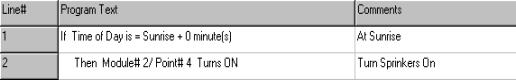
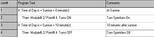
Each relay in the RLY8-XA™ is represented by a module number and a point number. The module number is the ADICON™ address of the unit and the point is the logical relay number (0 – 7) within each module. For example if the RLY8-XA™ is module 2 and you want to turn on relay 5 you would have C-Max™ turn on module 2/ point 4, see example below. The relay will remain on until instructed to turn off or the relay watchdog times out. The relay watchdog will be covered later.
Turning off a relay is similar to turning on a relay. See code below.
The relay watchdog is used to turn all the relays off if communication with the ADICON™ controller is lost. A value of 255 in the relay watchdog parameter will turn off the relay watchdog function, that is, once a relay is turn on it will remain on until instructed to turn off. Set the relay watchdog parameter to the number of seconds (1 – 254) to timeout after ADICON™ communication is lost. Zero is not a valid relay watchdog value.
Operation X10
X10 LED Codes
X10 led - On solid, X10 Mode.
X10 led – Blinks off when X10 activity detected
ACTIVE led – blinks a number of times to indicate the House Code. See Table 1
COMMS led - blinks a number indicating the code version.
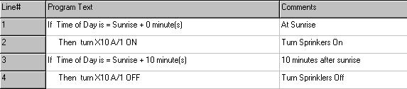
Each relay in the RLY8-XA™ is represented by a house code and a key code. The house code (A – P) is the X10 address of the unit and the key code (1 – 8) is the relay within the module. The examples below show how to turn a relay on and off using X10.
X10 Pulsed Relay Commands
Sending an X10 Dim command to a relay will turn the relay on for approximately 2 seconds.
Sending an X10 Bright command to a relay will turn the relay on for approximately 4 seconds.
Relay LEDs
Each relay has an LED to indicate when the relay is energized. These LEDs can only be seen when the top cover is removed.